
what are you looking for?
What are the precautions for using linear guides? 1. Prevent linear guide rails from rusting When holding the linear guide rail directly with your hands, wash off the sweat on your hands and apply good quality mineral oil before replacing them. Pay special attention to rust prevention during the rainy season and summer. 2. Keep the linear guide operating environment clean Keep the linear guide and its surrounding environment clean. Even if tiny dust invisible to the naked eye enters the guide, it will increase the wear, vibration and noise of the guide. 3. Install linear guide rails carefully. Linear guides must be carefully used and installed. Vigorous stamping is not allowed, the guide rail is not allowed to be directly struck with a hammer, and pressure is not allowed to be transmitted through rolling elements. 4. The linear guide rail installation tools must be suitable Use appropriate and accurate installation tools for linear guides. Use special tools as much as possible, and try to avoid using things like cloth and short fibers.
Read More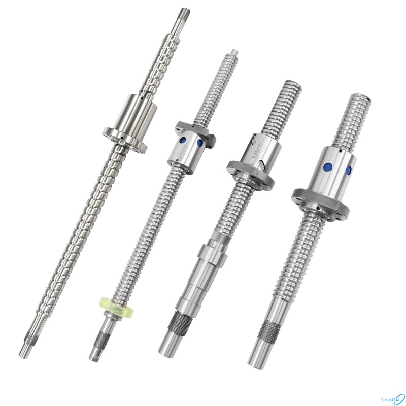
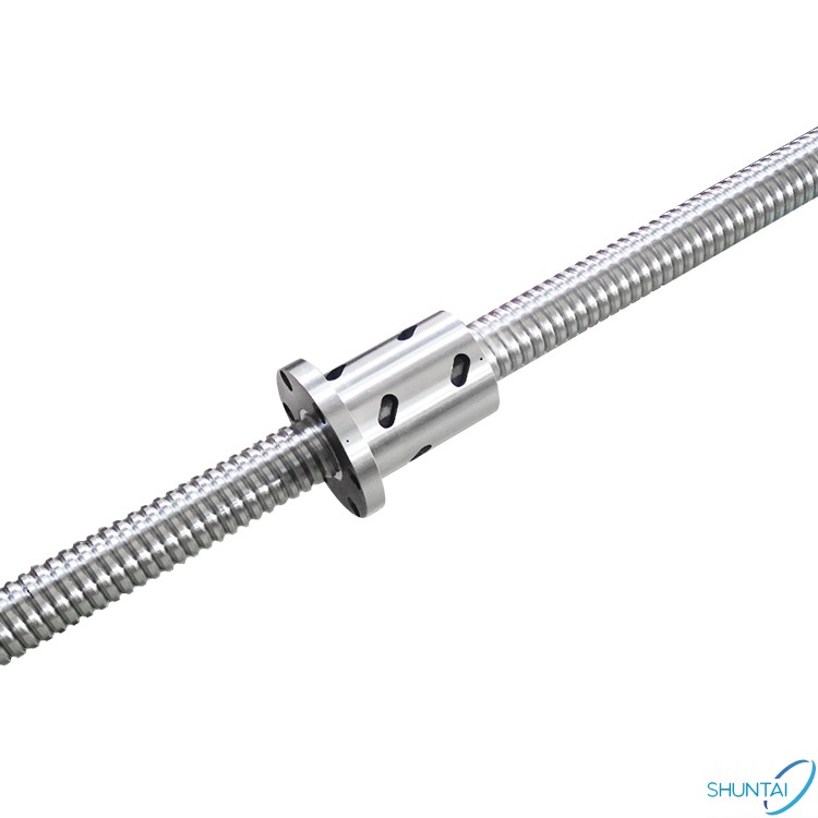
The difference between ground ball screws and rolled ball screws lies in the different processing methods. Ground ball screws are manufactured by mechanical processing, while rolled ball screws use a one-time forming method. Grinding ball screws are targeted at industries with higher precision requirements, and their use costs are higher. The precision of rolled ball screws is low, and the cost is low when used in industries that do not require high precision. Rolled ball screws are cold-rolled and have very low precision, usually C7 precision. Better manufacturers can barely achieve C5 precision, but one advantage is that the production cycle is short and the delivery time is fast. The production process of grinding-grade ball screws is relatively complicated. They are ground using ultra-precision grinding machines and require quenching in the middle. The accuracy can reach the highest grade C0, but the delivery time is very slow. Our company's grinding ball screw processing cycle is usually 30-35 days. In peak seasons when orders are large, it needs to be postponed for about 5-10 days. The rolling ball screw processing cycle is very short, and the construction period is usually about 5-7 days ( Orders must be placed in the order in which they are placed). Customers in need are welcome to discuss cooperation!
Read More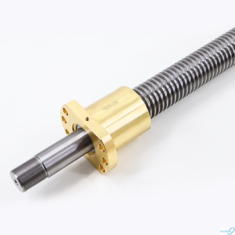
Trapezoidal screw materials: 1.General precision (referring to grade 7~9) Trapezoidal screws, for light loads, are usually made of non-alloy medium carbon structural steel (such as 45, 50 steel), normalized, quenched and tempered, or cold-rolled free-cutting steel (such as Y45MnV) Directly machined. For those with wear resistance requirements, quenched and tempered non-alloy structural steel (such as 45, steel) can be used, and it can be used directly after ammonia carburizing treatment. Screws used for measurement and with little stress can be made of quenched and tempered non-alloy structural steel (such as 45, 40Cr steel), which can be used after induction heating and surface quenching. 2.Precision (referring to level 6 and above) Trapezoidal screws are usually made of non-alloy (carbon) or low-alloy tool steel (such as T10A, T12A or 9Mn2V, CrWMn steel) for light loads, and are quenched and tempered or spheroidized annealed. Screws that work frequently are often made of low-alloy tool steel (such as 9Mn2V, CrWMn steel) and integrally quenched. They can also be made of high-grade nitriding special steel (such as 38CrMoA1A, 35CrMo steel) and undergo infiltration treatment to withstand high temperatures. temperature situation. Small-sized screws that require wear resistance can be made of carburized low-alloy steel (such as steel), and can be used after carburizing + quenching and low-temperature tempering. For screws that work at high temperatures, they can be made of precipitation-hardened stainless steel (such as OCr17Ni4Cu4Nb) and used after solid solution + aging treatment.
Read More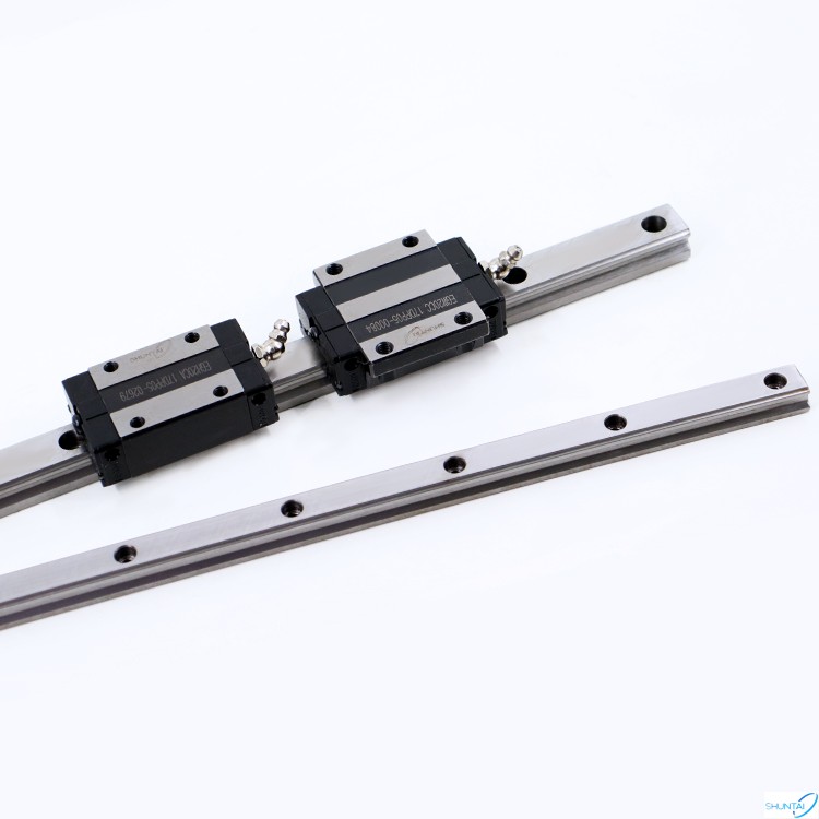
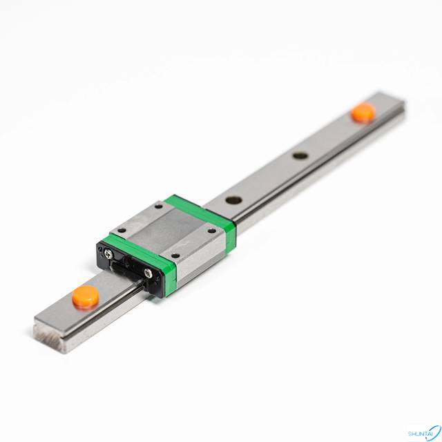
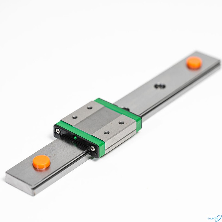
As an important moving component, linear guides are an indispensable component for many machines. So many customers need to install them by themselves after purchasing linear guides. What should they pay attention to when there are no technical personnel present? Let’s talk briefly today. You can consult our technical staff for specific operations. The first thing to note is not to remove the slider from the guide rail at will. Normally, we ship the slider and the guide rail together, which means that the slider is of good quality, because there are balls inside the slider. If you take it out without paying attention, it may cause the balls to slip. If the ball is lost, the slider cannot be used. Generally, our manufacturer will be equipped with a slider push-off device to assist in removing the slider and reduce the occurrence of ball falling off. In addition, disassembling the slider during assembly may cause dust and dust in the environment to fall in. After reinstalling, the motion may be stuck and the accuracy may be reduced, which is not worth the gain. So before the formal installation, we must first carefully clean the installation location, remove burrs, dust and other dirt on the work surface, and keep the work surface smooth and tidy. In addition, it is necessary to apply anti-rust oil to the linear guide rail to prevent rust from affecting the normal function and performance of the product in future use. Linear guide rails are usually fixed with bolts. Each model has a recommended bolt model. Customers are also asked to use the recommended sizes. When fixing the bolts, be sure to tighten them and keep the track and the workbench close to each other without shaking. After tightening them all, drive the hole cover into the assembly bolt to keep it on the same level as the top surface of the linear guide rail. There are some technical requirements for the assembly and installation of linear guides. We recommend that our customers find relevant technicians or consult the manufacturer for technical support during organization and installation.
Read More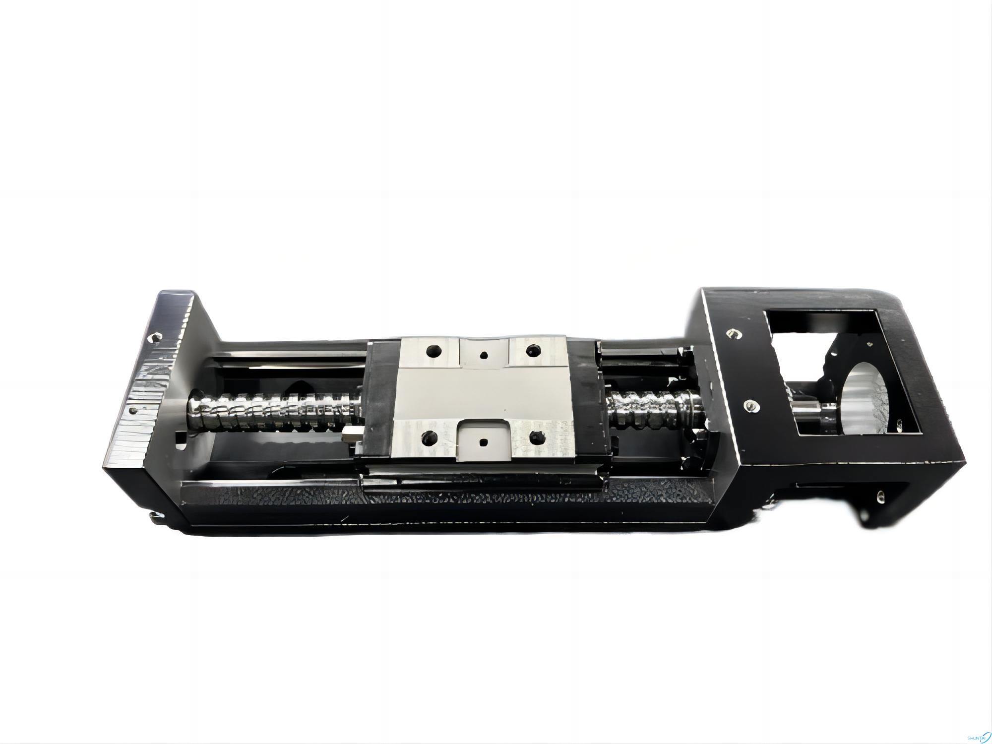
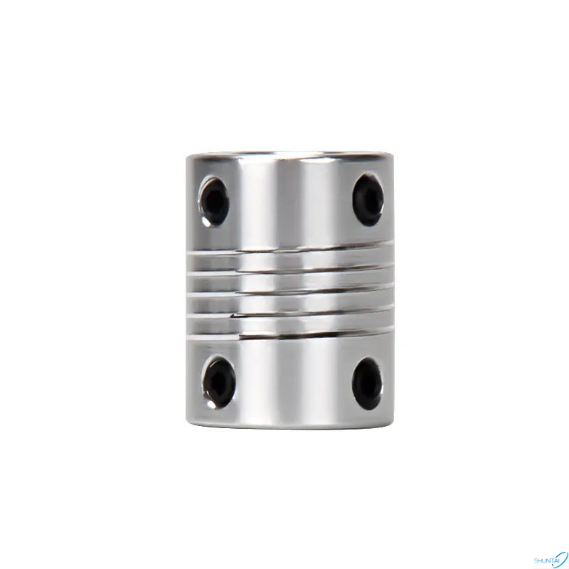
KK modules, like linear guides, play a significant role in the mechanical industry. Linear guide rail is a common and commonly used transmission accessory, while KK module is relatively less common. Today, let's talk about how to verify whether KK module can be used. This institution uses many modules, and the servo motor is used to drive the modules. The quick acting shaft in the motor is connected to the ball screw in the module through a coupling, and the motor works to drive the screw to rotate, thereby driving the entire machine to move. Regardless of the direction, servo motors are used in combination with modules to drive the vacuum disc to move materials up, down, up, and down. The central adsorption of materials also requires the use of cameras and light sources to detect the angle of material placement, and the ranking angle is adjusted through another servo motor. The selection of KK modules requires consideration of positioning accuracy and stroke, as different models of modules have different strokes.
Read More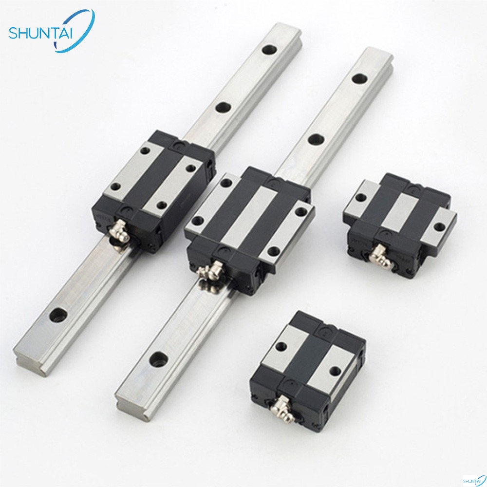
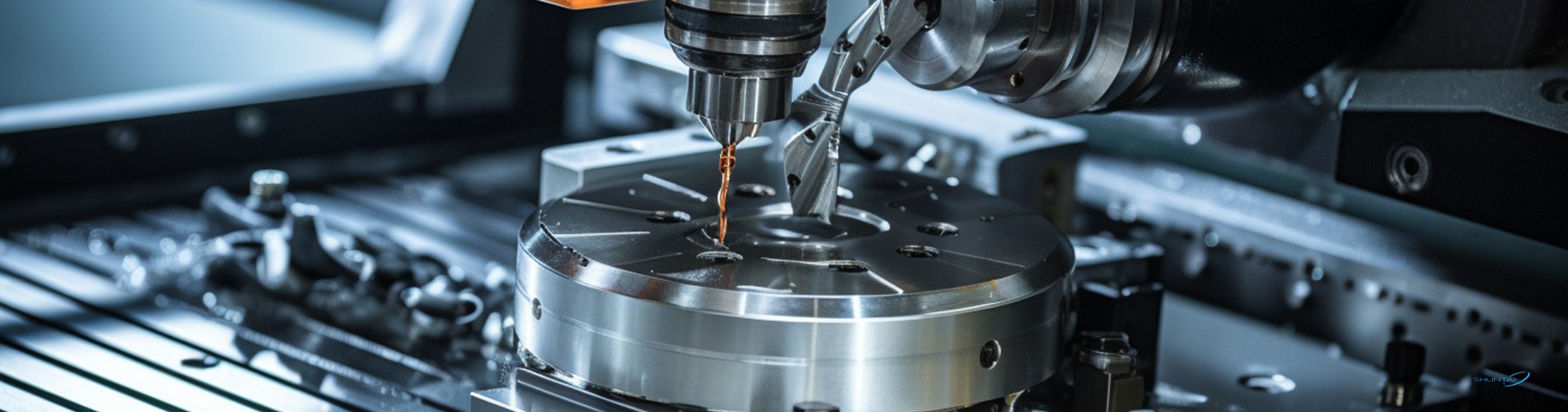
Linear guide rail is one of the basic components in machine tool machinery. It is widely used in various types of CNC machine tools, machining centers and other automation equipment. The application advantages of linear guides produced in our factory in machine tool equipment are mainly reflected in the following aspects: 1.Achieve precise linear motion: Our factory-produced linear guides provide precise linear motion so that various parts of the machine tool can be accurately moved and positioned. This is essential for achieving high-precision machining and measurement. 2.Improve production efficiency: The use of linear guides produced in our factory can significantly increase the processing speed and accuracy of machine tools, thus improving production efficiency. At the same time, because the friction coefficient of the linear guide is small, it can reduce energy consumption and improve energy efficiency. 3.Reduce operating costs: The use of linear guides produced in our factory can reduce reliance on skilled operators and reduce labor costs. At the same time, due to the high precision and long life of linear guides, the maintenance and replacement costs of machine tools can be reduced. 4.Adapt to various working environments: The linear guides produced in our factory have the advantages of high rigidity, high precision, high load capacity, etc., and can adapt to various harsh working environments. For example, linear guides can still maintain stable performance in environments such as high temperature, low temperature, moisture, dust, etc. In short, the application of linear guide rails in machine tool equipment can significantly improve the performance and efficiency of the equipment, reduce operating costs, and adapt to various working environments.
Read More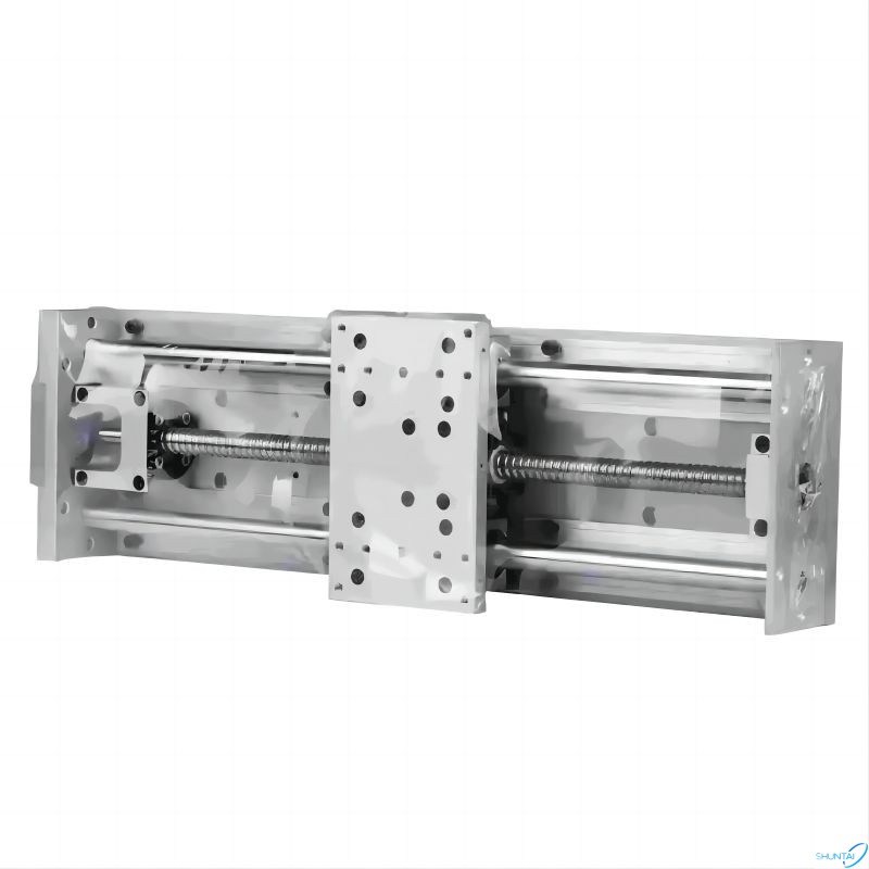
KK module, also known as single axis robot or linear module, plays an important role in the mechanical industry and can also be applied in multiple industries. Application on machine tools: Choosing high-performance and reliable CNC systems, servo drive devices, and high-quality supporting components in machine tool design can greatly improve the reliability of CNC machine tools. Application in the painting industry: 1.Automatic spraying and painting machines: can reduce labor and save spraying raw materials. 2.Automatic book retrieval machine: used for large library management equipment, easy to manage. 3.Automatic dispensing machine: can reduce manual labor and save spraying raw materials. Applications in light industry, textile, printing and dyeing industries: bleaching and dyeing, spraying, crystal handicraft processing, etc. Applications in the electronic semiconductor industry: batteries, IT fields, precision welding, motor welding, sensors, refrigeration parts welding, light guide plate marking, cables, LCD panel edges, integrated circuit (IC) marking, welding parts laser, soldering tin are all applications of linear modules. Applications in the medical and pharmaceutical industries: Single axis robots are used for marking plastic mechanical covers, detecting, sorting, and packaging during drug transportation. In the transportation and logistics industries, applications such as handling, palletizing, sorting, etc. can greatly save costs and complete all operations safely and efficiently.
Read More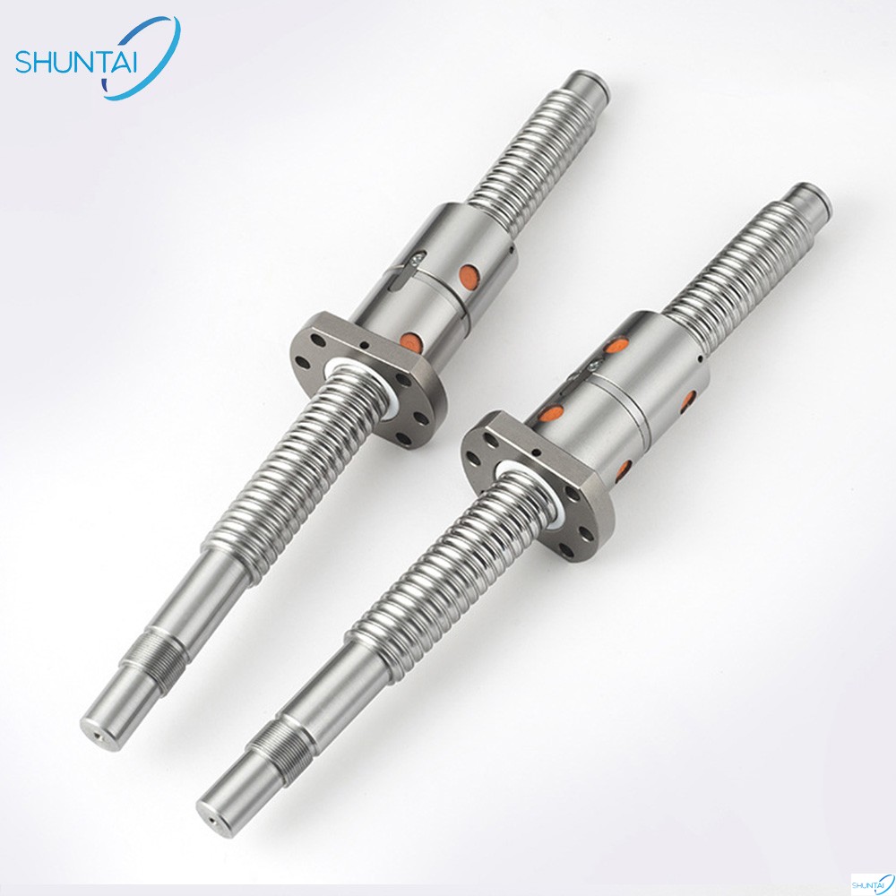
Firstly, take a look at the requirements of your device and clarify these parameters: accuracy, load, stroke, speed that requires automation, etc. ① Precision: The ball screw has grinding rods and rolling rods, which have different precision and higher grinding accuracy. Therefore, if the equipment requirements are high, the grinding rod should be selected. ② Load: The larger the diameter of the screw, the better its rigidity, and the greater the load it can withstand. ③ Lead: determines the speed of carrier movement, and the lead of the screw refers to the distance the screw rotates one turn to move the nut. The larger the value, the faster the speed. ④ Pre pressing: refers to the pre tightening force between the nut and the screw, and the pre pressing is adjusted by selecting steel balls with different diameters. ⑤ The flange installation hole spacing of the nut should match the equipment.
Read More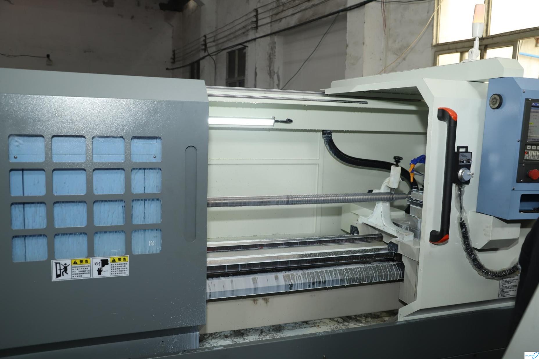
There are many processes and procedures for making ball screws, and grinding is a very important part of it.This is also one of the advantages of our factory, superior grinding technology. The high-quality grinding in our factory mainly focuses on the following aspects: 1. Choose high-precision and high-stability grinding equipment to ensure the smooth progress of the grinding process. 2. According to the material and precision requirements of the ball screw, select the appropriate grinding wheel material and particle size to ensure grinding efficiency and surface quality. 3. Select special coolant to prevent overheating, burns and other adverse phenomena during the grinding process. 4. During the grinding process, control the feed speed of the grinding wheel to avoid undesirable phenomena such as overcutting and undercutting. 5. Reasonably control the grinding force to avoid damage or deformation of the workpiece. 6. During the grinding process, the grinding wheel needs to be dressed in time to ensure the sharpness and surface quality of the grinding wheel. 7. Develop a reasonable grinding process and strictly follow the process to ensure the quality and accuracy of each processing link. 8. Accuracy testing is required at each processing stage to ensure processing quality and accuracy.
Read More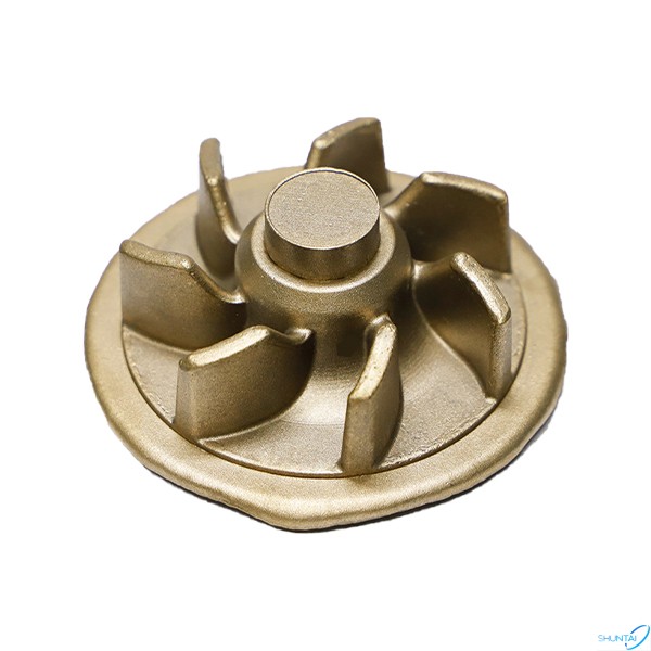
Our company has extremely rich experience in custom manufacturing CNC machining, milling and turning aluminum parts. We can manufacture castings of different types and materials. Today we focus on impeller castings. Let me give you an in-depth understanding of this casting product.The picture below is a physical picture of the impeller. Impellers are critical components in various industries including power generation, aerospace and fluid mechanics. In the world of power generation, these superb blades sit at the heart of turbines and determine large-scale electricity production. Its function is to pressurize or convert energy to the flowing liquid or gas. Commonly used materials for impellers include cast iron, cast steel, cast aluminum and non-metallic materials. According to their structures, they can be divided into closed impellers, semi-open impellers and open impellers. Among them, the closed impeller is composed of blades and front and rear cover plates. Since there is no underflow loss in the closed impeller, the efficiency is high. Closed blades usually have irregular curved surfaces with large warpage, thin wall thickness, and high quality requirements such as dimensional accuracy, shape tolerance, and surface roughness. We will take the feasibility and reliability of casting production into consideration when manufacturing, because these ultimately determine the quality of castings. Therefore, we will summarize and establish an internal mold design experience database to minimize the occurrence of multiple changes in the later period due to insufficient consideration of the casting process during the design process.
Read More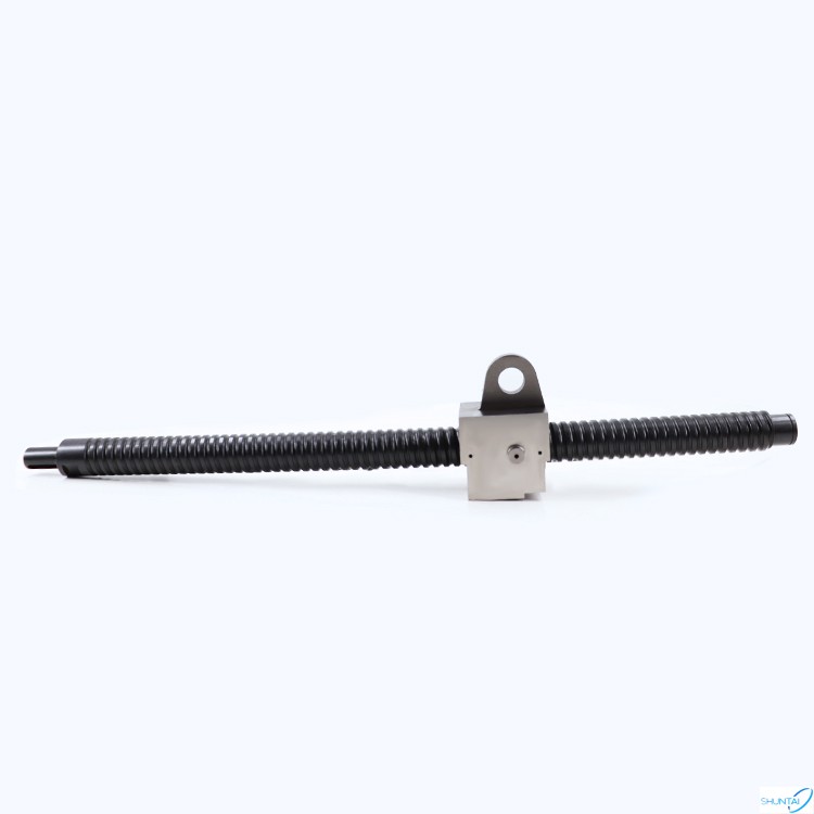
We are a factory that mainly manufactures ball screws and can provide customized special-shaped ball screw services. The following are the general steps for customizing ball screws in our factory: 1. Design drawings: Customized ball screws are generally made according to the design drawings provided by the customer, or special drawings can be drawn for the customer according to the customer's requirements. 2. Confirm requirements: Communicate with customers to understand specific requirements and applicable solutions. Determine the requirements for ball screw diameter, length, lead, accuracy grade, material, load capacity, speed requirements, etc. 3. Processing and manufacturing: According to the customer's design drawings, advanced CNC machine tools and other equipment are used to perform turning, milling, grinding and other processing on the screw, and finally complete the manufacturing of nuts and the installation of balls. 4. Product quality inspection: After the ball screw is processed and manufactured, the product is subjected to appearance inspection, dimensional inspection, accuracy inspection, motion inspection, load capacity inspection, rust prevention inspection and other tests to ensure that the product meets customer requirements. 5. Confirm the product: After completing the quality inspection of the ball screw, contact the customer to confirm the product. If there are any problems with the product, timely communication and negotiation of solutions are required. 6. Delivery and after-sales service: Finally, according to the customer's requirements, the customized ball screw is packaged and delivered to the customer through the designated transportation method. After the customer receives the product, the corresponding after-sales service is provided, including installation guidance and maintenance support, etc.
Read More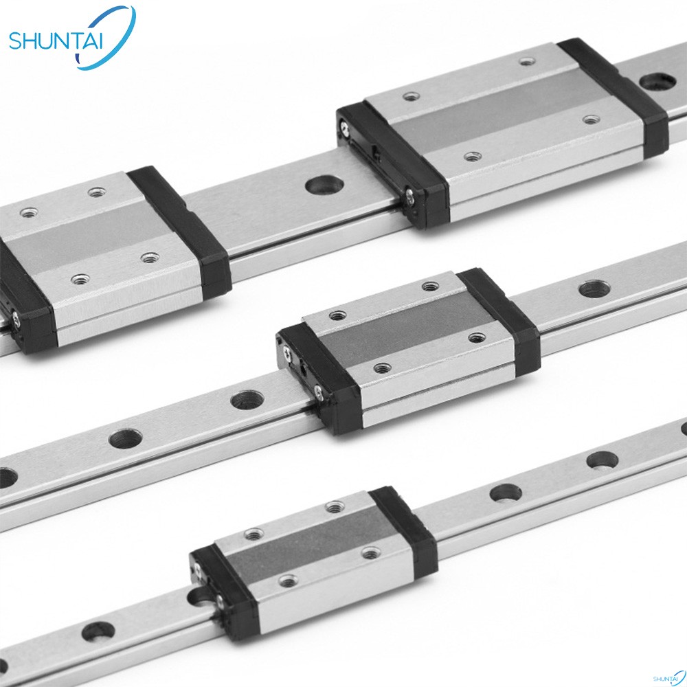
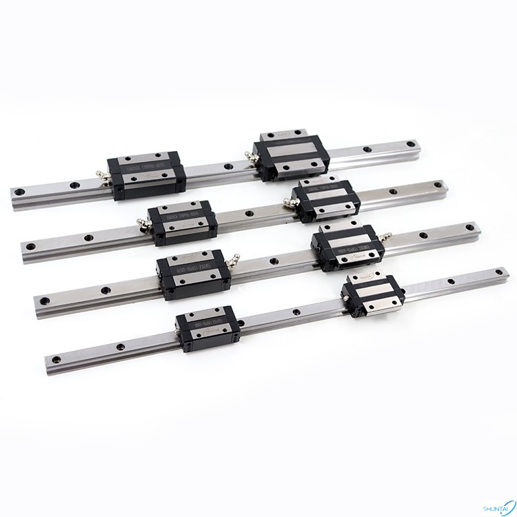
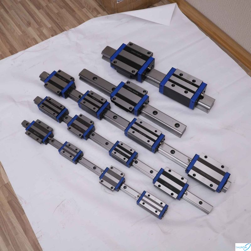
Linear guide rail is a commonly used linear motion guidance device in mechanical systems. According to different structures and working principles, linear guides can be divided into various types. The following are some common types of linear guides: Sliding guide rail: Sliding guide rail is the simplest type of linear guide rail, which uses sliding to achieve linear motion of the workpiece. Common sliding guides include sliders and guides, sliders and sliders, as well as sliders and positioning screws. Rolling guide rail: Rolling guide rail achieves linear motion of the workpiece through rolling elements (such as balls or rollers), with high rigidity and accuracy. Common rolling guides include ball screw guides, roller guides, cylindrical guides, etc. Linear motor guide rail: The linear motor guide rail integrates the guide rail with the linear motor, and drives the motor to generate linear motion, achieving high speed and high acceleration linear motion. Linear motor guides are widely used in high-performance fields such as automation equipment, medical devices, and semiconductor equipment. These are some common types of linear guides, each with its specific advantages and applicable scenarios. When selecting a linear guide, it is necessary to choose based on specific application requirements, load requirements, accuracy requirements, and speed requirements.
Read More
 SIGN UP FOR OUR NEWSLETTER
 IPv6 network supported